While working on my projects, I did several attempts to depict Mazda CAN protocol, to find useful information. For example, getting the shift position for the “smart “mirror project and the fuel level for the fuel reminder. There are many products available for the OBD2 protocol. One good product is TouchScan with Mazda extension, which allows you to access every module in the car for diagnostic purposes. Using this tool, I figured out how to get access to the fuel gauge on the console, instead of using the sensor in the tank. However, while it is a very useful tool, it does not provide access to real-time information available on CAN bus as broadcasted messages.
OBD2 protocol is query-respond based. You can get information by sending a request to the addressed module, but this is not the same as getting information from live broadcasted messages, without any delays.
Mazda uses two separate buses, HS-CAN or High-Speed 500khz and MS-CAN Medium Speed 125 kHz. It is well documented in the Mazda Work Shop manual, but without actual IDs for each module, which is proprietary Mazda’s information, not available for public.
I decided to make a dual-channel CAN logger/bridge, which will allow me to record messages from individual modules as well as logging from two buses. I found an old Raspberry Pi board, which will be perfect for this project. Two SPI CAN modules on top of it will do the job.
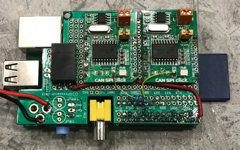
Assembled with CAN-SPI modules
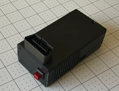
“Black box” 3D printed enclosure with an illuminated push button to start/stop logging.

Accessible USB ports for memory stick and Wi-Fi dongle.

Logging started
Using Python programming language it will be easy to do filtering and bridging between CAN segments for separate logging on a common bus and individual modules.

My goal is to figure out how to control warning sounds, get access to the switches on the steering wheel and central console as well as some basic information, like speed, steering position, etc., in real-time.
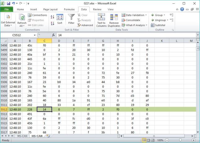
First, I logged 10 minutes drive and converted it into an Excel spreadsheet. The next step will be logging from individual modules, using bridge option in my sniffer.
Started my list MX-5_CAN (updated on 3/14/17), shift position, wheels speed, steering column angle decoded, work in progress…

Some useful links:

Pingback: Raspberry Pi Zero W for car applications | Gadgets for my MX-5 2016 (ND)
Hello great article have you made any progress on further decoding? I am looking at making my mazda autonomous
LikeLike
Hi, I am going to do CAN bus decoding, though my ND is still in factory.
Do you know this decoding information? It is for Mazda 6 but seems some common IDs.
https://github.com/majbthrd/MazdaCANbus/blob/master/skyactiv.kcd
The original article of the above is:
http://www.2x4logic.com/mazda-canbus.html
LikeLike
Mazda6 seems very different. I will update my list soon, but my focus was on key fob messages, instrument cluster info…
LikeLiked by 1 person
actually I was wrong, there are many common IDs
LikeLike
As far as I tested on ND’s instrument cluster, turning signals (ID 0x09A; offset 20, 21) worked.
You can see how I tested. (texts are Japanese, but browsing photos will be enough).
https://minkara.carview.co.jp/userid/2898510/car/2508605/4641612/note.aspx
LikeLike
What pins are the respective busses on?
LikeLike
on OBD connector: pin 6 – HS-CAN-H, pin 14 HS-CAN-L
pin 3 MS-CAN-H and pin 11 MS-CAN-L
LikeLike
Thanks!
LikeLike
I got HS-CAN access working with an MCP2515 and a Pi, but for some reason MS-CAN doesn’t return any data via candump
Did you run into any issues trying to access the MS-CAN?
LikeLike
MS-CAN must be configured for 125 kbps speed, otherwise was no problem. Also, I found that all the messages on MS-CAN you can catch on HS-CAN as well. Probably some device has bridge between them.
LikeLike
This might be useful to you. I did some CAN sniffing today while developing a new aftermarket race car dash 🙂
“Mazda 6 Skyactive 2.2 diesel, manual transmission 2017 model CAN definitions”
“HS (500kHz bus), all wordss big endian”
CAN i.d.
0x78 “Bytes 0,1” “Bytes 2,3” “Bytes 4,5” “Bytes 6,7”
Unknown | “Least significant 4 bits of byte 3, and byte 4 (12 bit value)” | Unknown
Brake pressure – scaling/units unknown.
Offset by 152 decimal – ranges from 0x98 to 0x1FF
0x202 “Bytes 0,1” | “Bytes 2,3” | “Bytes 4,5” | “Bytes 6,7”
Engine RPM x4 | “Vehicle speed, km/h x100″ |”Throttle position, TPS% x 640” | Unknown
0x240 Byte 1 All other bytes unknown
Steering torque – scaling/units unknown
“7F in centre position – clockwise reduces value, anti-clockwise increases value”
0x420 Byte 0 | Byte 7
Engine coolant temperature | Ambient air temperature
Scale = Deg C +30 Scale = DegC +30
LikeLike
Have you made any progress here? I found some values by myself, referenced some others from your findings and consolidated everything I was able to verify so far into a spreadsheet. If you have anything more I’d be glad to put it in there as well 🙂
https://docs.google.com/spreadsheets/d/1esu8ZwbGdsSdRScDTRIpWefJDRQ3cWEFa1ea_2i-GMk/edit#gid=1082866376
I’ve not scanned MS-CAN so far as the info there is of no use to me so far
LikeLike
you can add to 0x9F , Byte 0 , Bit 0 is indicator of reverse, to trigger backup camera. Ox472 is status of roof for RF. MS-CAN data will appear on HS-CAN, because it is bridged on IC
LikeLike
I’ll validate this asap, because the reverse switch is connected to the PCM while 0x9F is being sent from the IC. I don’t have an RF or Automatic, I can add the IDs to the specific Control unit if you have a filtered list.
LikeLike
I’ll validate this asap, because the reverse switch is connected to the PCM while 0x9F is being sent from the IC. I don’t have an RF or Automatic, I can add the IDs to the specific Control unit if you have a filtered list.
LikeLike