Mazda MX-5 2016 GT has advanced safety features, like Lane Departure Warning System (LDWS ) and adaptive High Beam Control (HBC).
Here is the Mazda document, showing how it works. This is the manual for Mazda 6, but MX-5 is identical.
I’m not sure about the value of having LDWS on a sport car, like MX-5. It often produces false alerts which is quite annoying. Disabling this feature by turning it off will show up as a yellow warning light, which is also annoying. I’ve not had a chance to test the HBC feature yet. So, I was thinking to turn this camera into a dash cam, by hacking it or even replacing the whole PCB.
I found on eBay this camera from a salvaged MX-5 2016 and decided to do some reverse engineering to better understand potentials. My hope was also to find a video output from CMOS sensor to use it as a source for video recording.


Camera is assembled in a die casted aluminum enclosure, with a tin cover without any screws (bended tin tabs hold it together). PCB inside is attached to enclosure by 4 screws near the connector and camera sensor. Very solid construction, no internal connectors.

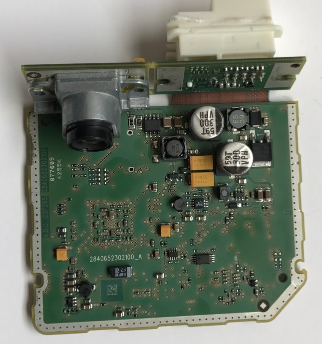

Looks like “blast from the past”, 10 year old technology.
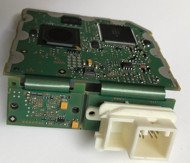
Video processing done by old TI DSP TMS320DM643 which is obsolete now.
CAN communication processor from Renesas MR32/ECU 192 which is also obsolete.
There is also 16 Mbit SPI Flash memory M25P16, probably holding code for DM643, because MR32 has integrated Flash memory. There is also DDR2 512Mb (16 x 4Mbyte) chip connected to the DM643.
I could not figure out yet what CMOS sensor is there. The lens holder seems glued to PCB with epoxy, covering chip. I did capture i2c traffic on sensor, now need to find out which manufacturer uses “4c” address for its CMOS sensor.

Vertical interval 30ms and Horizontal interval 50μs with 16 MHz clock, which translates to 800×600 pixels image resolution for processing. Video data seems to use 8bit parallel bus.
Camera has a 10 pin connector, but only 4 pins are used for power and CAN. Other pins routed on PCB, but components not populated .

Updated 1/30/2017:
Based on i2c scan, image sensor there is Aptina MT9V024 WVGA 1/3″
Interfacing with FSC implemented over HS-CAN bus, PID 0x706. Below list of available options. To catch live events I will do more logging with my new CAN sniffer.

Updated 2/17/2017
I decided to take video out from the camera using LVDS serializer chip MAX9235, connected to the parallel video bus on the FSC board. Since the main connector has a few unused pins, I will use 2 pins to transfer serial video data out of the box.

For now, I put the MAX9235 chip on the little breakout board and connected it by wires

The receiving side will convert the parallel bus from the MAX9206 to the CSI-1 bus using the TI SN65LVDS315 chip, which I can connect directly to the Raspberry Pi camera interface. Raspberry Pi will act as the video recorder and format convertor. Using its NTSC output it will be possible to bring video to the CMU console, the same way as the backup camera is connected.
to be continue…

I found that identical camera can be found in many other vehicles . It is designed and manufactured by German company Continental AG
http://www.continental-automotive.com/www/automotive_de_en/themes/commercial_vehicles/chassis_safety/adas/ldw_lks_en.html
Firmware probably customized for each brand.
LikeLike
can’t wait to see part2
you give me an inpiration
LikeLike