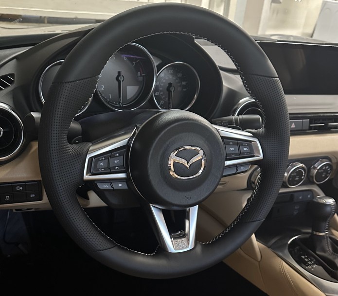
The Mazda MX‑5 ND already has a great soft‑top design. Putting the roof up takes just a few seconds, but folding it down does require a bit of force to lock it in place. It’s easy enough when you’re standing outside the car, but from the driver’s seat it can turn into an awkward shoulder move. As I’ve gotten older, that last push has started to bother me. So I decided to add a small assist mechanism to my 2024 MX‑5 ST/GT to make that final step effortless, letting the roof drop into place on its own.
The main idea was to implement a motorized hook that would lower the top to the locking position. I had several simulations using SolidWorks, but to test these ideas, we (with my friend) built a roof mockup. I found an eBay roll bar and roof frame. This mockup was very helpful for figuring out all the mounting options and testing some components. Many parts of this assembly were 3D-printed, but load-bearing parts machined on a CNC machine.
When the top is locked down, the motor releases the cable so that, once unlocked, nothing obstructs the top from being raised. Activating the top‑lock switch makes the motor lower the slider, hiding it from the rear view. Unlocking the top latch reactivates the electronics, prompting the motor to release the cable again. This allows two Constant Force Strip Springs to return the slider and hook to their active position. When the top engages with the hook, the limit switch triggers, the motor pulls the mechanism downward, and once the top locks, the motor releases the cable again. The electronics then return to sleep mode.
This project came with plenty of challenges, mainly because the space inside this car is extremely limited. I wanted the system to be as simple and clean as possible, using plug‑and‑play electrical components like I do in most of my builds. Some of the existing holes in the car were too large, so I designed extra parts to properly mount the motor and main panel. Another key requirement was that the manual operations had to work even if the automatic system failed or the battery died. And overall, I aimed to make the smallest changes possible to the car itself.
After multiple iterations, I finally made a reliable mechanism.

There are a couple of unavoidable alterations to the car’s plastic panels; one is a new hole in the plastic back cover (seat back bar lower ganish) for the hook/slider. This panel is not very expensive, and I got a new Mazda part to modify it. Second is a hole through the glove box compartment, which was easy to drill with a 36m Hole Saw. I 3D-printed a cylinder to insert into this hole, so that inside the glove box, it covers the holes. Other than this, everything else uses existing mounting holes. Motor secured by two M5 nuts, main assembly by two M4 screws

I chose the motor from the 2014 Mazda 3 window regulator mostly for its slim design, so it can fit easily under the cover panel. It also uses the same stall-sensor implementation as the MX-5, so I could reuse my window-controller design for the MX-5 with the exact same electronics. Of course, I have to design new firmware for this application.


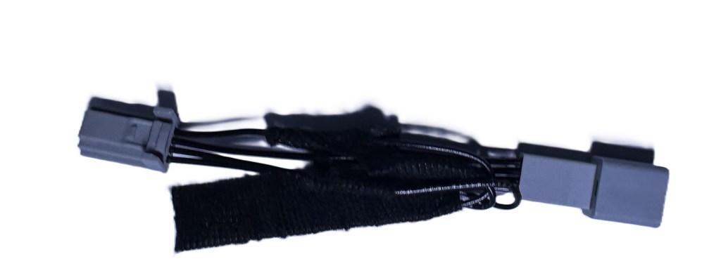
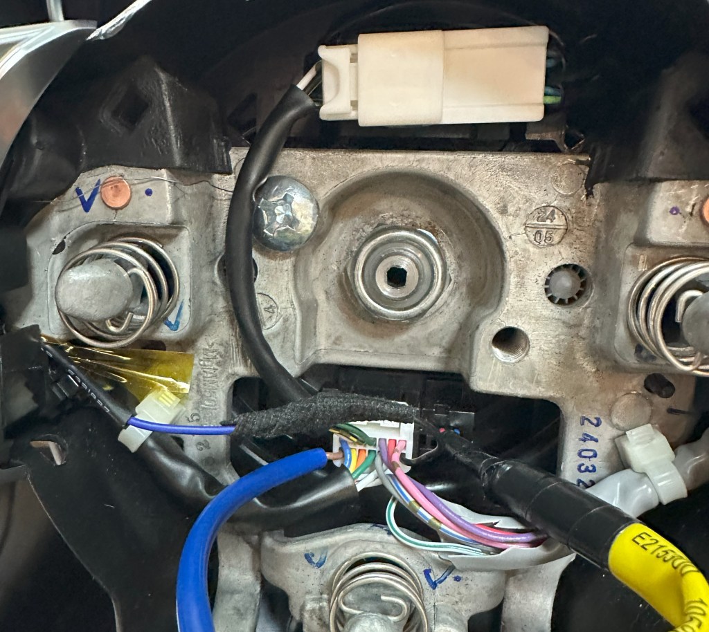
The only new thing I have to design is a harness connecting the motor, controller, and sensors from the top lock (on top of the windshield), along with a sensor from the back side of the roof mechanism, and the power line. Fortunately, all these wires are available on the back side of the car, on the car radio amplifier unit (with Bose system). I made a male/female harness for an amplifier for a real plug-n-play setup. Controller connected to a constant Battery power line and goes to sleep mode after 30 seconds of any action. This allows us to operate with the top in any situation, whether the car is turned on or off.

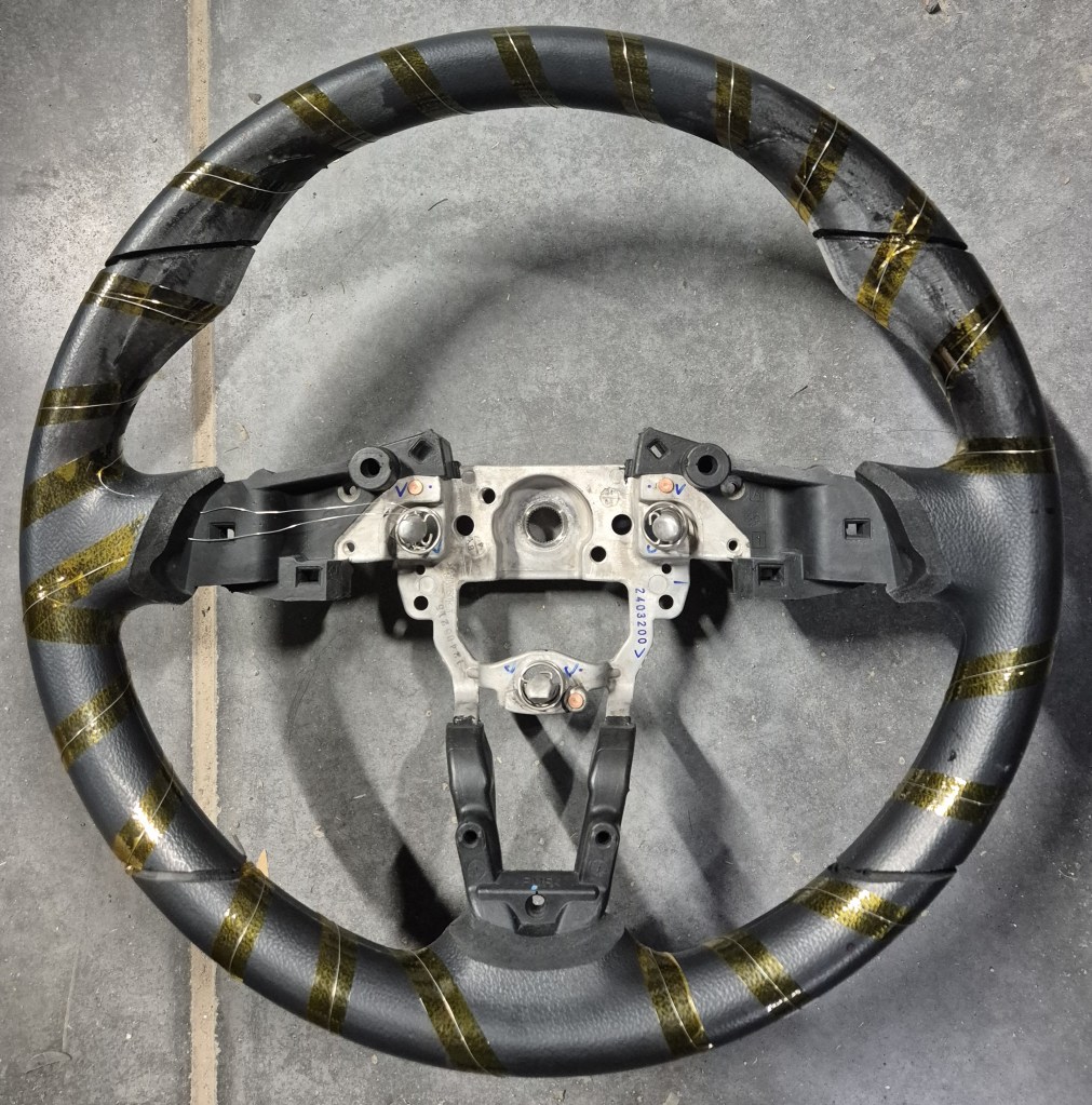
The installation process was time-consuming because we had to remove many plastic panels to access the roll bar. There are only 4 screw to remove, and everything else is on plastic hooks and clips. But in the end, it was easy to put all the panels back. Probably a couple of hours to install and an hour to put everything back. Mazda has detailed instructions for removing all the panels, available online here.

This was a very challenging but exciting project because it involved mechanical design, electrical engineering, and firmware development. Special thanks to a member of Miata.net, Jumperthumper, for assisting with the initial mockup.


You must be logged in to post a comment.