Speed Correction Module

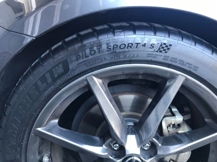
I recently decided to change the tires on my car to Michelin 215/45ZR-17 MICHELIN PILOT SPORT 4S because the original size 205 was not in stock anywhere. After more research, I think size 215 will look better. However, the downside of this is that the diameter of that tire is 0.3″ bigger, which will cause incorrect odometer counting. Here is the calculation using the Miata.net calculator:

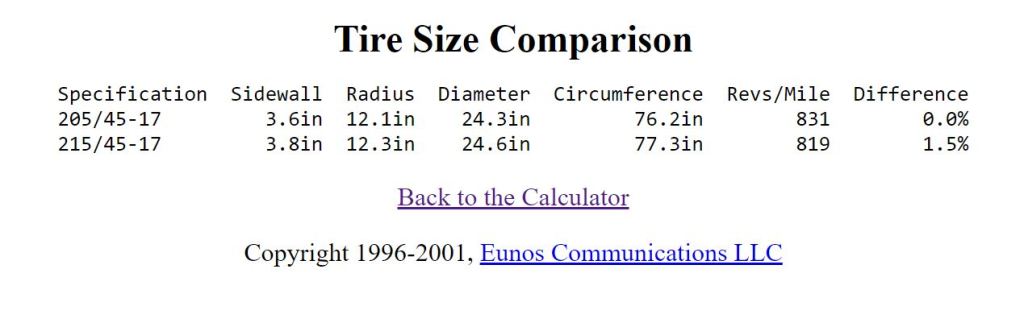
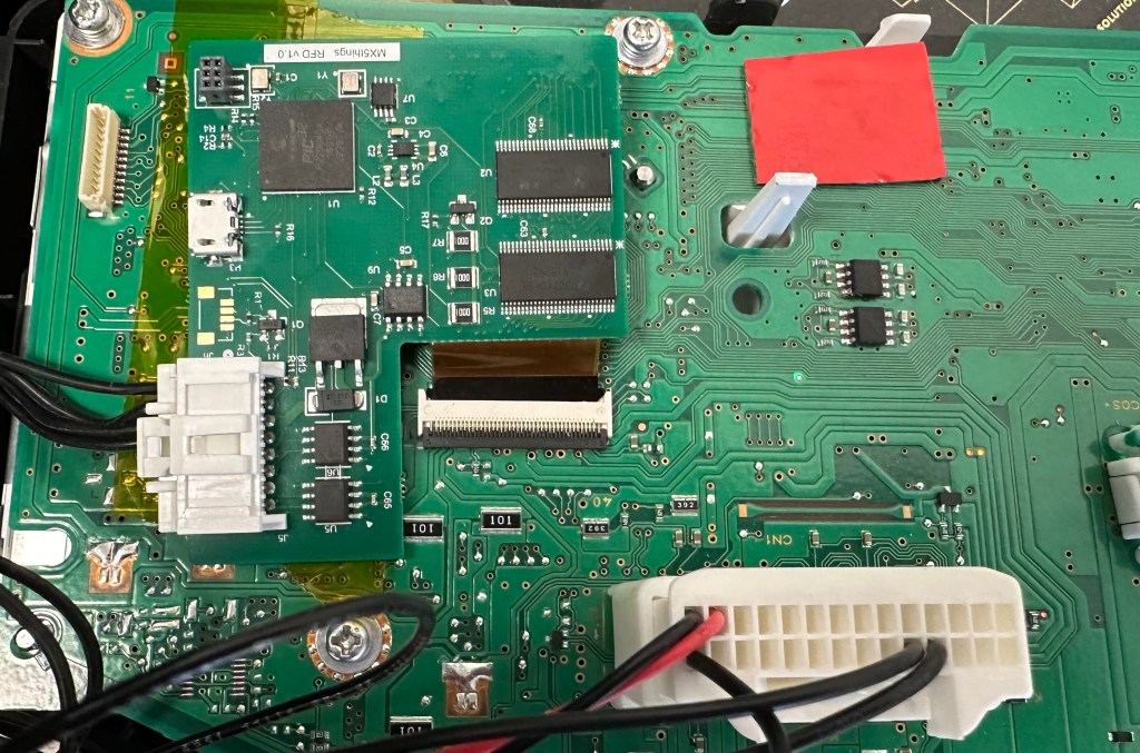
This means that the speedometer will show 60mph, while the actual speed is 60.9mph and the odometer will show a lower value over time (150miles less for every 10,000). It is not a big deal, but for sake of accuracy, I decided to correct this with one of my devices. In the Mazda MX-5, the Instrument Cluster gets information about speed via CAN bus, from message ID 0x202. I used these messages for my digital speedometer implementation. So, to correct the speed information all we need is to intercept this CAN message and recalculate in real-time, according to the Tire Size Calculator. My RF roof controller is basically doing the same thing with speed info, to override the default speed limit of 6mph. I can reuse the same hardware design for correcting speed in the Instrument Cluster. All that’s needed is a new plug-n-play harness attached between the Instrument Cluster and the main harness. I think this device will be useful for people who want to/or have changed wheels size or any non-OEM size tires.

Hacking RF Instrument Cluster display

The Mazda MX-5 RF has a graphic LCD screen as part of the Instrument Cluster. I thought it would be cool to access it to show additional information on that screen. The LCD is 4.6″ with an FPC cable to the mainboard. The LCD is controlled by the graphic processor Yamaha YGV642, which would be the perfect option for customization. Unfortunately, Yamaha denied my request to share the datasheet and I could not find anything in the public domain. I decided to use an external graphics processor and implemented a video switch, to control the LCD. To accelerate development, I chose the Microchip development board and made a simple PCB with connectors and a video switch.

Of course, it is bulky, but I got immediate access to the LCD screen and can start work on software. The LCD screen has a resolution of 432×432 pixels with a simple RGB interface, 6 bits per color, with a 62 Hz frame rate. I was able to synchronize my processor with Yamaha, which allows me to insert a portion of my graphics and leave some untouched. My first test was the implementation of a digital counter.

The first project is the implementation of the digital speedometer. Current speed is available on the CAN bus, so it makes it easy to capture it using just one wire soldered to the mainboard, directly to the Rx output of the CAN receiver chip. Switching from “mph” and “km/h” is also available through CAN messages. I implemented this as well. The speedometer comes on screen after four clicks on the “Info” button, and the next click will turn it off.  During the road test, I found that the digits switched too quickly when the speed was on the borderline of the next number. To avoid this I implemented a simple filter, averaging 32 samples. Now it is perfect.

The next project will be an implementation of an analog clock, which will show up when the engine is turned off and stay until you open the door, or click the Info button to another feature.

The power reserve handle will show the battery’s voltage, which will be useful to see when the engine is off.

I will design a smaller single PCB with a microprocessor and FPC connectors, to make installation simple. CAN bus is not present on the FPC connector, so one wire needs to be directly soldered to the mainboard. The software can be updated at any time via USB cable.

Work in progress!