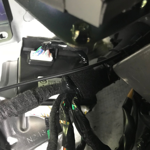
When replacing turn signal incandescent lamps with LEDs, the typical problem is hyper flashing. This happens due to the car diagnostic reporting a drop in power consumption, and to get attention from the driver to check the bulbs. LEDs typically consume much less power. One easy fix is to add a resistor, to compensate the load. But the value of this resistor must be considered carefully. The most common advice on YouTube videos is to install 6 Ohm 50W resistor, which will dissipate 30W of heat (average will be 15W, due to 50% duty cycle of the blinker, but still it is a lot of heat)… Also, if you replace only one bulb, it will completely defeat the diagnostic. If the LED bulb malfunctions for some reason, there won’t be any notification. I decided to check BCM implementation, to get a better understanding of this issue. The photo below shows BCM module from the Mazda MX-5 2016.


Wires from the front and rear lights are coming to the different connectors, but on the PCB they are directly connected to the same switch (see red circle on the photo)
Main microcontroller is NXP (Freescale) SPC5603B. Other chips there are:
UJA1078A – high-speed CAN/dual LIN core system basis chip
TLE7244SL eight channel low-side switch with SPI interface
TLE72592GE transceiver for the Local Interconnect Network (LIN)
Turn signal switch implemented on Infineon BTS5020 Dual High Side Power Switch. This switch is very sophisticated. It provides all kinds of protection and diagnostics. On the picture below is a typical connection diagram (from the data sheet).
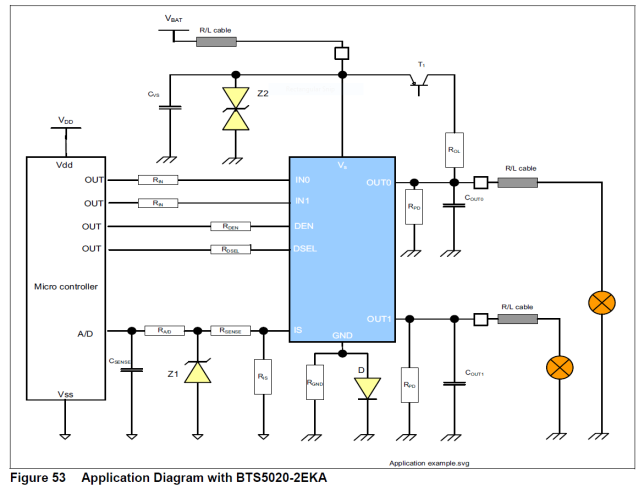
As shown on this diagram, all the diagnostics come from a single IS pin. R-is resistor will define voltage for the ADC on the Micro controller. I did a test with variable load and found that hyper flashing starts when the load drops below 40W.
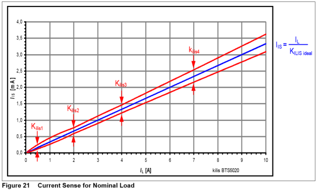
It is more likely that a threshold is set for 3A current through the switch, generating 1mA on the IS pin.
The ideal option would be software modification, but it’s also possible to simply change the value of the sensing resistor for the new estimated load. By changing the value of this resistor, we can tune the threshold for hyper flashing. The resistor on the board is marked as R108 and has a value of 1.3K, for the maximum load of 27W+21W+5W (53W total).
Off course this modification is not for everyone. I think it is a better solution, instead of adding high power resistors and disabling real-time diagnostic.
To test this approach, I replaced the R108 resistor with a 3.2k value resistor, and replaced the front 27W bulbs with LEDs from iBrightstar (4W power consumption). Without high power resistors, the hyper flashing starts only if I remove the LED bulb.

The BCM module is very easy to access. It is located under the dash on the driver side. There is no single screw, everything is held by plastic hooks. It took me 20 minutes to replace the resistor and reinstall BCM in place.

G’day!
I have just purchased /ordered your rear sequential rear led indicators and I also want to install front led indicators and led side markers. What ohms resistor would I need to fit in the bcm for this type of fit out? Would I still need the resistors you supply with the sequential led lights plus the bcm mod or will just the bcm mod be enough? Here in Australia the globes (bulbs) are 21w front and rear.
Thanks in advance.
Philip Menezes.
esphil.menezes@gmail.com
LikeLike
Hi Philip, if you going to replace resistor in BCM, you don’t need to use extra harnesses. 4.3K resistor will be good for this mod.
LikeLike
Is there a trick to removing the BCM? I have a Fiat 124, and it is impossible, it seems, to reach the clip at the top of the BCM with my hand. Perhaps the Miata isn’t as tight?
LikeLike
I think you can just pill BCM and it will come out. Clip is very soft. You can just try to push it down with flat screw driver
LikeLike
Hi, I saw you successfully took the BCM out.
It is very difficult in an MT, and I am still unable to reach the tab on top.
How did you do it? What tool did you use?
Please let me know.
Thanks,
Yushi
LikeLike
I did not use any tools, just finger on top
LikeLike
Thanks Sergey.
This was a question to Stephen Whiteley.
I know you could do it with finger. In an MT, clutch pedal and brackets are in the way and I cannot get my finger to the tab. I wonder how he did.
Thanks,
Yushi
LikeLike
Hello Sergey,
What is the size of the chip resistor for R108? Is it 0402? or 0603? It appears smaller than 0805, although the land pattern seems to accommodate it.
My LEDs draw 0.8A per side for front and rear combined, and perhaps 5W (0.4A?) for the side turn light, so approximately 15W total. What is the appropriate value for R108 in this case? Would that be around 3.9k if I wanted to make the threshold around 1A (12W)?
Please let me know.
Thank you.
Yushi
LikeLike
it is better to use wires, so you can easy replace value. Check this thread https://www.124spider.org/threads/bcm-modification-for-regular-led-lights.31782/
LikeLike
Hello, it’s Marco from Italy.
Thank you very much for your article, it gives me hope. I have a Toyota Yaris Hybrid MY18 and I’m trying to swap to led turn signals without adding resistors. The hyper flash is controlled by the instrument cluster (on older Yaris there was a flasher relay), here you can find the electrical wiring diagram of the turn signal:
https://www.dropbox.com/s/5jp3c6cgajvfm43/10%20turn%20signal.pdf?dl=1
According to your experience is it worth to buy a used instrument cluster and try to apply your solution?
Thank you.
Marco
LikeLike
you can try, send me a photo of the PCB when you get it.
LikeLike
Ok, thank you!
LikeLike
Hello, today I opened the instrument cluster. Here you can find 2 photos (1 photo and 1 scan) and all pdf files I have. Tell me if you need also the photo of the other side of the PCB.
https://www.dropbox.com/sh/chpbbiopu28f2db/AAChqiu0dwlqz5WBmtQqbA6Ea?dl=1
Thank you very much for your help, I wish you all the best for this Christmas.
LikeLike
yes, we need good photo of other side of PCB. Please use email info@mx5things.com for future communication.
LikeLike
Hello Sergey,
I have recently tried to retrofit the Headlamp cleaners to my 2016 MX5 using original parts. I noticed it’s not functioning because the BCM is not pulling the control side of the relay to ground. After asking Mazda about it I got told it’s a software restriction by VIN / Region. Did you tap into the BCM software at all?
LikeLike
no, I did not
LikeLike
Theoretically, would you be able to figure out which part of the software is responsible for it, assuming you’d be able to pull it from the controller of course and getting it to work with a re-flash? I tried getting around the issue buying a second BCM and tricking the IDS-Software into taking the software from a car known having it equipped. Didn’t work.
LikeLike
Unable to find any information on the what I presume to be the main controller (SPC5603BCLL4) I was hoping you would be able to know some source for a datasheet. Currently trying to retrieve the software off the chip somehow.
LikeLike
https://www.nxp.com/part/SPC5603BF2MLL4#/
LikeLike
I have started on the washer project. I wonder if you have any details you could share
Kent
LikeLike
Would the resistor you used work if I have replaced both the front and back blinkers with LEDs?
Right now my front blinkers are using these bulbs that are advertised to stop hyper flashing. They do (for about 3 minutes, then I get hyper flashing). I assume these guys just have a resistor built in?
LikeLike
Yes, it will work for all combinations. To make easy adjustments, you can use a trimmer resistor, 20K, so you can control from 0 to 20k. Start with middle position 10K. The goal is to stop hyper flashing when all lights are connected and make sure it will start hyper flash if you remove one bulb.
LikeLike
Do you have pictures of the backside of the BCM PCB?
LikeLike
I will post it soon.
LikeLike